
Chain oiler for the Kawasaki Versys 650
3 installation reports for this model

Installation report by MR.D.
Kawasaki Versys 650 – year of manufacture 2019
This is how MR.D. solved the installation – unfortunately we cannot guarantee that it works correctly, as we were not able to check the installation ourselves.

Oil reservoir 60 ml
Behind the left side panel
Metering valve
On the left-hand side of the frame, behind the cylinder.

Nozzle
Mounted underneath the swingarm with an adhesive pad.

Switched 12 V supply
Tapped at the front in the instrument panel via a splitter at the USB socket connection (already prepared), white-red wire.

Rain switch
Here: position of the filler neck – integrated into the switchgear on the left.

Control unit
Fitted upright directly behind the battery.


Installation report by Micha
Kawasaki Versys 650 – year of manufacture 2019
This is how Micha solved the installation – unfortunately we cannot guarantee that it works correctly, as we were not able to check the installation ourselves.
Oil reservoir 60 ml
I fitted the standard oil reservoir crosswise under the seat at the rear
Metering valve
Lying crosswise directly next to the onboard tool bag.
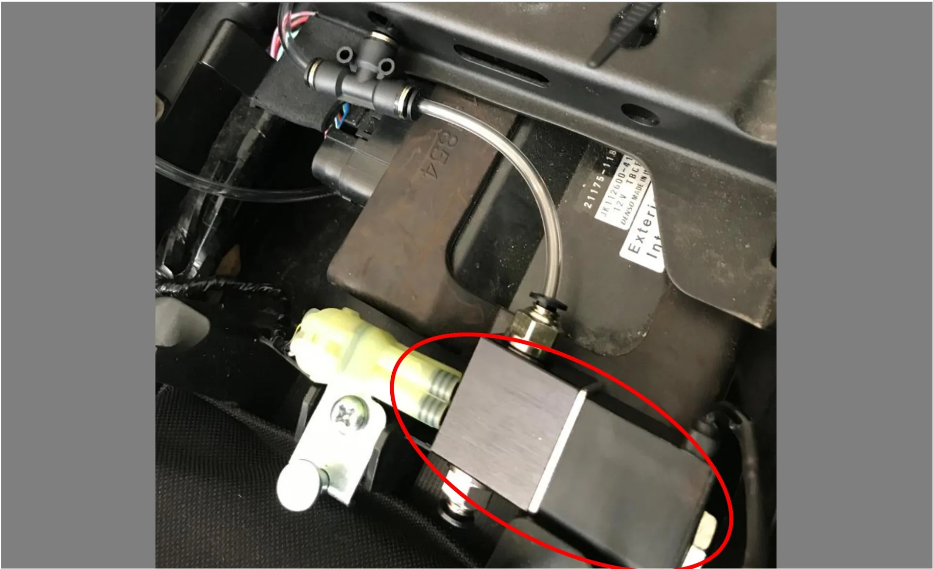
Nozzle
Mounted underneath the swingarm with an adhesive pad. Nozzle at the 6 o’clock position.

Switched 12 V supply
Plugged onto the black/white terminal at the horn.
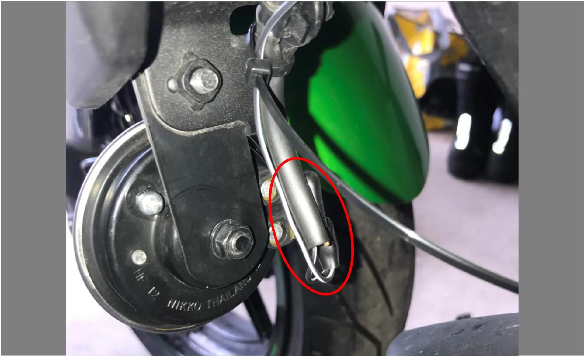
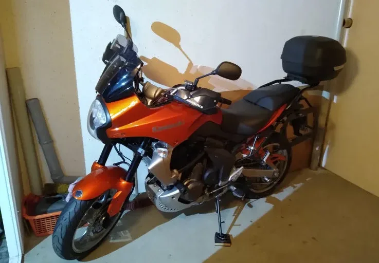
Rain switch
On the left mirror mount – cable routed under the fuel tank – parallel to the wiring harness.

Control unit
Fitted upright directly behind the battery.

Installation report by Ben
Kawasaki Versys 650 – year of manufacture 2007
This is how Ben solved the installation – unfortunately we cannot guarantee that it works correctly, as we were not able to check the installation ourselves.

Oil reservoir 120 ml
Under the rear fairing on the left-hand side of the frame (with the variable reservoir vent in addition).
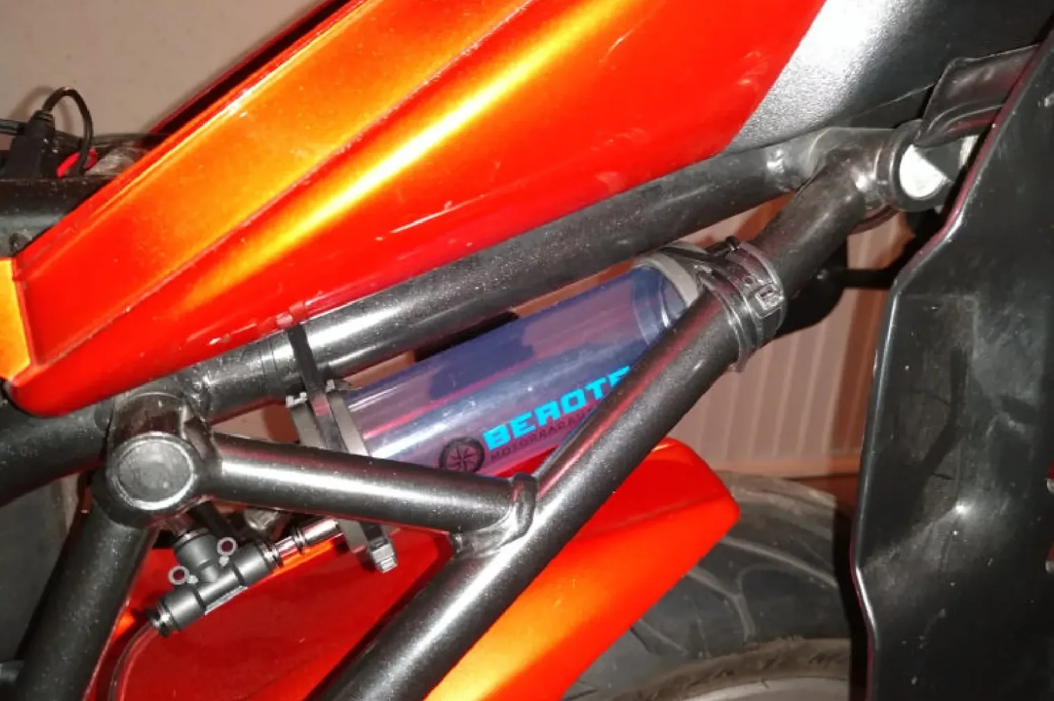
Metering valve
Fitted near the pillion footpegs with a home-made bracket (heat protection sleeve fitted downwards to the nozzle).
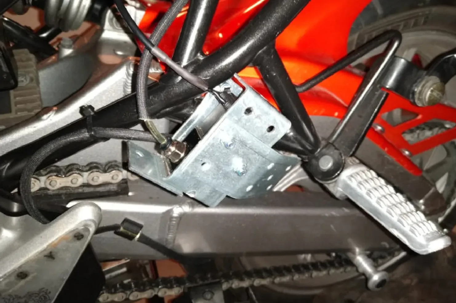
Nozzle
At the rear sprocket, hose routed along the underside of the swingarm.

Switched 12 V supply
Soldered to the horn and then secured with heat-shrink tubing and insulating tape.

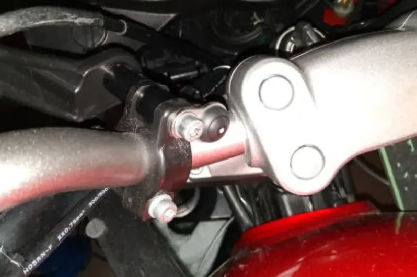
Rain switch
Attached to the hand guard mount.
Control unit
Under the seat, in the document compartment.

Have you fitted a MOFESSOR? Contribute your own installation report – directly here, with your photos.


