
Chain oiler for the Triumph Tiger 800 XRx
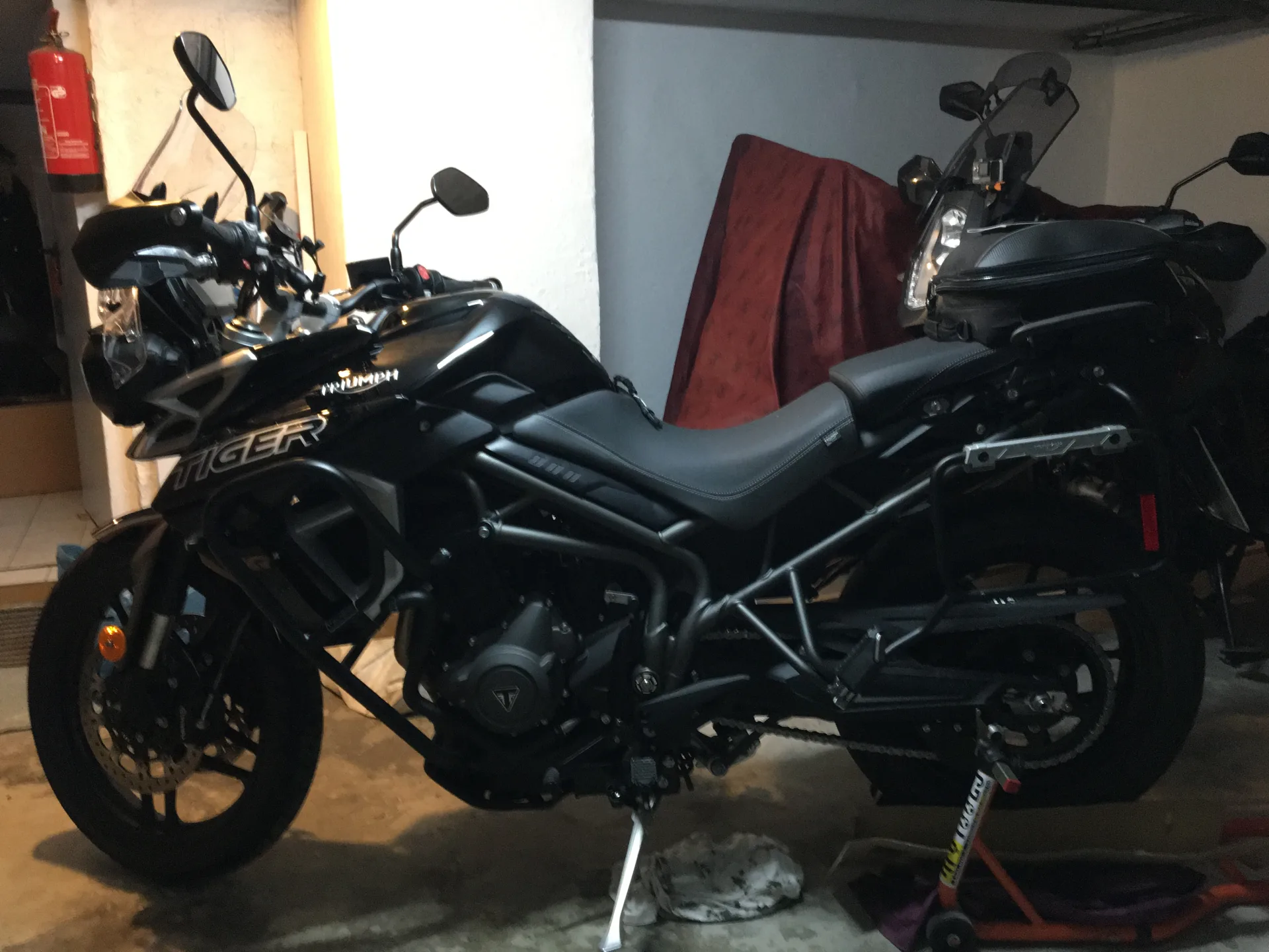
Installation report by LUV
Triumph Tiger 800 XRx – year of manufacture 2019
This is how LUV solved the installation – unfortunately we cannot guarantee that it works correctly, as we were not able to check the installation ourselves.
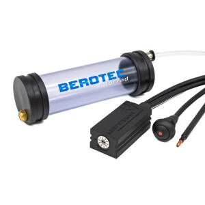
Oil reservoir 60 ml
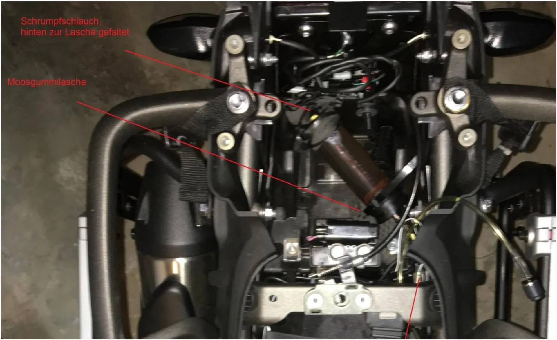
The oil reservoir was tilted slightly forwards and mounted elastically (at the rear a rubber mount made of heat-shrink tubing to push onto the existing plastic tabs, at the front a bolted foam rubber tab with releasable cable ties), placed in the tail unit under the luggage rack cover. The fill level can be seen without removing the cover, after taking off the pillion seat.
Metering valve
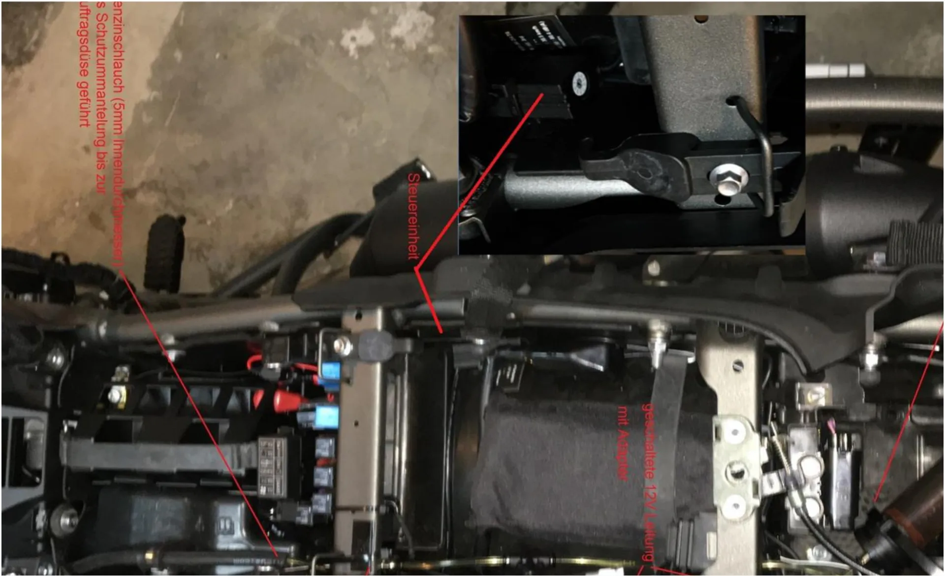
The metering valve is held in place with cable ties under the frame gusset plate. Shifting or tearing out the hose connections is virtually impossible, as the frame plate has the valve “firmly in its grip” from above.

Nozzle
The nozzle is fitted on the outside of the rear sprocket at 7 o’clock with the clamp. A fuel hose with an inner diameter of 5 mm was also pulled over the oil hose, to protect the hose against kinking when the suspension compresses and against chafing. The nozzle is then bent with the widest possible radii: a) towards the rear sprocket, so that the opening of the nozzle rests lightly against it; b) at the other end, bent inwards under the swingarm, so that the hose can be led into the opening on the inner side of the swingarm. The hose can be routed forwards through the swingarm and comes back out in front of the shock absorber.

Switched 12 V supply
On the left of the frame under the pillion seat there is a white six-way connector (male, with five switched connections). On the XRX it is not used as standard. After removing the blanking plugs, the female connector can be wired up with suitable terminals. Switched +12 V was found at the connection shown, on the green wire. Ground and permanent positive are also present, but were not used. Using the existing connector and suitable pins (female), an adapter was built in order to be able to connect further components later if required. Before wiring, it is advisable to check the actual pin assignment with a voltage tester, as according to some research the wire colours can apparently vary (depending on the model year). Here, switched +12 V was green, ground black and permanent positive brown (not red, as one might assume). The adapter cable was wired as follows: permanent positive = red | ground = black | switched positive = yellow Only the yellow wire was used as the ignition signal; permanent positive and ground were tapped directly at the battery.

Rain switch
The rain switch is mounted on the left on the clutch and mirror bracket. The cable is routed as far as the steering head parallel to the left switchgear cables, in order to ensure enough slack for the steering lock. From the steering head onwards, the cable runs on the left below the fuel tank, in order to keep enough distance from the ignition coils and the like.

Control unit
The control unit is secured on the right in front of the diagnostic connector with a clip-on cable tie in an existing hole in the plastic wheel cover.
Have you fitted a MOFESSOR? Contribute your own installation report – directly here, with your photos.


