
Gear Indicator & Oil Pressure on KTM LC4 and LC8 – Retrofit and Technical Basics
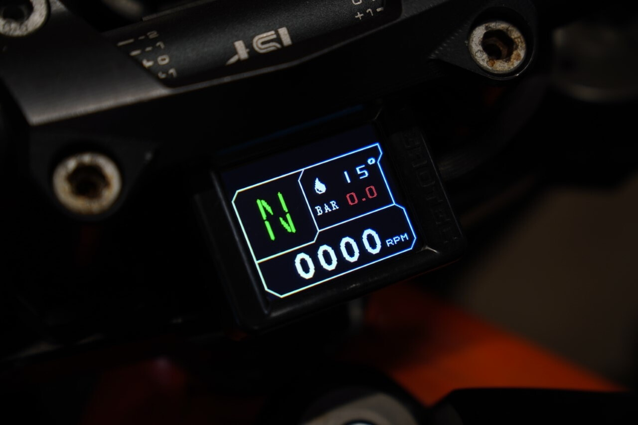
This article describes, as an example, the installation of the CUMPAN on a KTM Super Duke 990 R. The installation steps are representative for KTM models with an LC8 engine from 2003–2013 as well as for KTM models with an LC4 engine from 2007–2013. The focus is on retrofitting a gear indicator and integrating an oil pressure sensor.
In detail, this applies to the following models:
- KTM LC4 models from 2007–2013: 690 Duke | 690 Enduro (R) | 690 Rally | 690 SMC (R)
- KTM LC8 models from 2003–2013: 950 Adventure (S) | 950 Super Enduro (R) | 990 Adventure (R) | 990 Super Duke (R) | 990 Supermoto (R/T) | 1190 RC8 (R)
Installation steps
- Installing the sensor for oil temperature measurement
- Connecting the RPM signal
- Installing and connecting the gear sensor
- Installing and connecting the oil pressure sensor
- Power supply connection
- Settings on the CUMPAN
The following components are required for the installation described – depending on the engine type:
Shopping list LC4
- CUMPAN Cockpit Assistant
- Add-on module: Gear indicator
- Add-on module: Oil pressure sensor
- ACC splitter 3-way (optional)
- Display mount (optional)
Shopping list LC8
- CUMPAN Cockpit Assistant (950 and 990)
- CUMPAN Cockpit Assistant (1190 RC8)
- Add-on module: Gear indicator
- Add-on module: Oil pressure sensor
- ACC splitter 3-way (optional)
- Display mount (optional)
Installing the sensor for oil temperature measurement
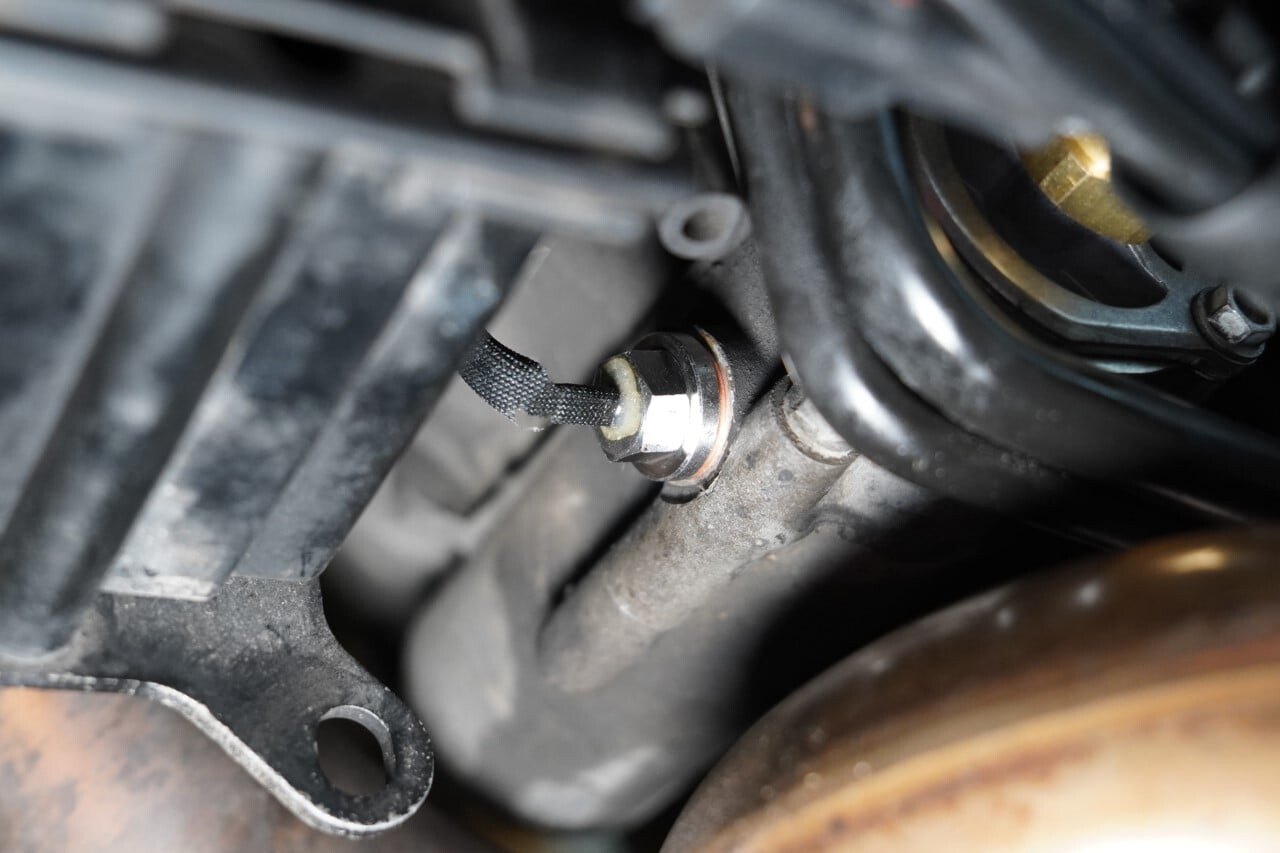
For the LC8 engine, we choose the M14x1.5 temperature sensor and install it at the front (in the direction of travel), at the bottom of the engine housing (position no. 7), directly at the oil filter seat. For better access on the Super Duke 990, the belly pan and the battery tray are removed. The original plug screw can then be removed and the M14 temperature sensor installed (observe a tightening torque of 20NM). Any oil that escapes must be collected and the corresponding amount replaced afterwards.

The 1190 version of the LC8 engine has a different crankcase, so the temperature sensor (M10x1) must be installed at position no. 27 (please check compatibility using the diagram!).
On the LC4 engine, three installation locations (position no. 3) can be chosen; the M10x1 temperature sensor is used for all of them. The first position, which is in the direction of travel, is located at the water pump housing and measures coolant temperature. The other two positions measure oil temperature.
When selecting the temperature sensor and the installation position, make sure the thread length of the sensor is suitable and that the sensor is not mounted in an exposed external area where it can be easily damaged.
Connecting the RPM signal
On the LC8 engine, the signal cable from the crankshaft sensor exits the engine housing on the right-hand side of the engine (position no. 1). This cable leads to a white 2-pin connector, where either the RPM signal tap or a PRESSLOK™ tap connector can be installed.
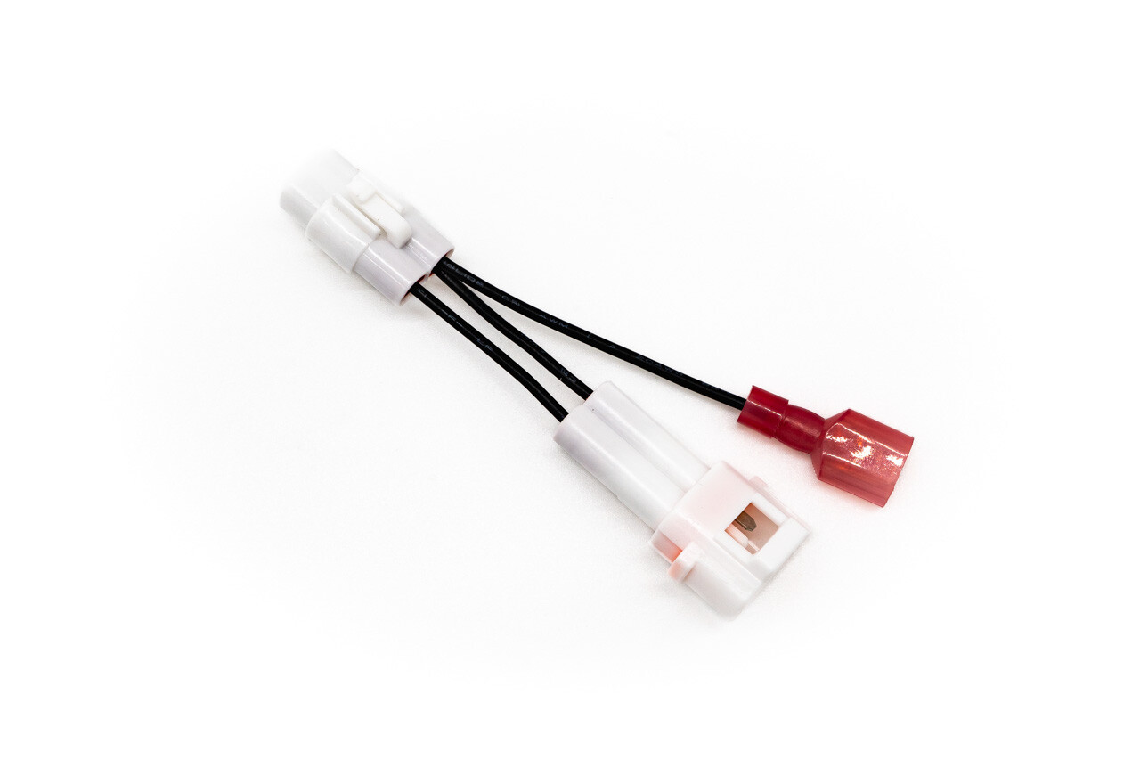
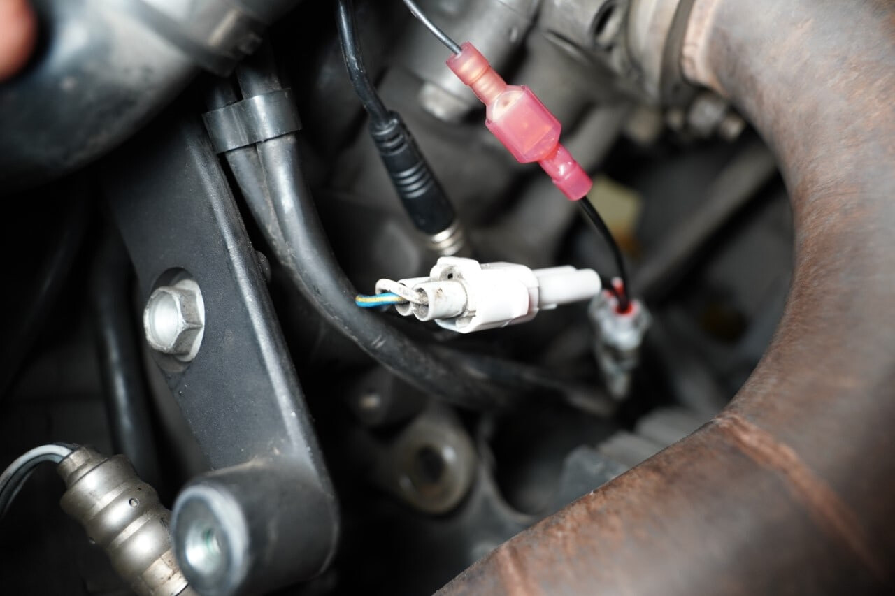
On the LC4 engine, the signal cable from the crankshaft sensor exits the engine housing at the rear right-hand side of the engine (position no. 17). This cable leads to a white 2-pin connector, where either the RPM signal tap or a PRESSLOK™ tap connector can be installed.
Important: The RPM signal is on the white/yellow wire. The pin assignment within LC4 and LC8 models can vary, i.e. when using the RPM signal tap the pins may need to be swapped so that the tap is on the line of the white/yellow wire.
Installing and connecting the gear sensor
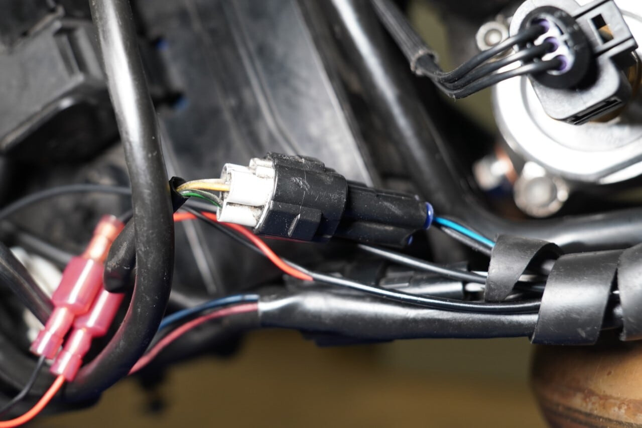
On the LC8 engine, the gear sensor is located on the left side of the engine at the height of the side stand (position no. 25). For removal, the two screws of the gear sensor and the 3-pin connector must be loosened. For better access, the side stand can be removed, although this is not strictly necessary. Installation of the new gear sensor is performed in reverse order (observe a tightening torque of 6NM), as is reconnecting the connector.
The 3-pin connector provides the original signals for the ECU. The 2-wire power cable provides the 12V supply for the gear sensor electronics and must be connected to a switched 12V supply. The ACC2 connection is suitable for this, for example.
The black/white wire carries a 0–5V voltage signal that provides the information about the selected gear to the CUMPAN. This wire must be connected to analog input 1 or 2 of the CUMPAN using a PRESSLOK™ butt connector.
Installation on the LC4 engine is almost identical; the gear sensor is also located on the left side of the engine at the height of the side stand (position no. 32).


Note: The original gear sensor detects neutral as well as 2nd and 3rd gear. The ECU uses the information whether 2nd or 3rd gear is engaged to reduce power at full load in these gears. This reduction is required to comply with emissions regulations.
For racing use, deactivating this reduction may be relevant; this only requires disabling the line for 2nd and 3rd gear. To do this, either remove the pins from the 3-pin connector or cut the wires (insulate any open contact points!). The wire color assignment is as follows:
- Neutral – green / green-black (sensor side / vehicle side)
- 2nd gear – blue-red / grey (sensor side / vehicle side)
- 3rd gear – yellow-green / yellow-brown (sensor side / vehicle side)
Note: Both the gear sensor and the oil pressure sensor require a switched 12V supply as well as a separate signal line to the CUMPAN. The respective sensor signals are captured via the analog inputs (IN1 / IN2).
Installing the oil pressure sensor (LC8)
Position 1
In this position, the oil pressure sensor is installed in the oil filter cover (position no. 6). First, remove the oil filter cover and collect the oil that runs out. The drained amount should be refilled accordingly afterwards. Make sure no contaminants enter the oil circuit.
The oil filter cover already has a recess in the center on the inside, which serves as a centering point for the pilot hole. Once the pilot hole has been drilled, the bore should be chamfered and then the thread (M10x1) cut. The oil pressure sensor must then be sealed with PTFE tape or another sealant and installed. The sensor is mounted on the outside of the cover. Finally, the oil filter cover can be reinstalled (observe a tightening torque of 6NM).
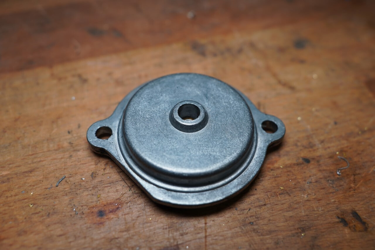
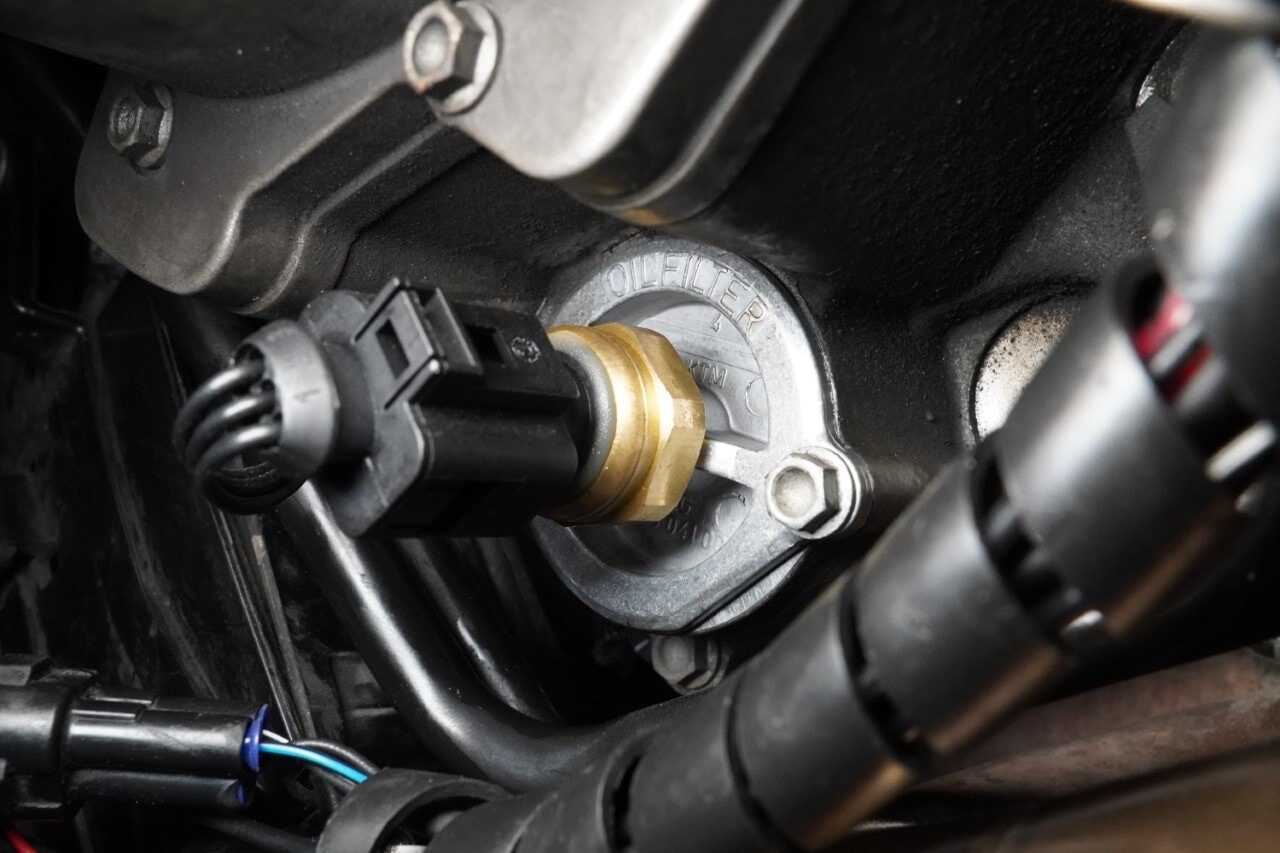
Position 2
Another possible position for the oil pressure sensor is at the cam chain tensioner (position no. 15).
This position is used by KTM itself; however, a reducer from M16 to M10x1 is required (part number: 60029006000, position no. 17).
Depending on the LC8 model, this position may be more suitable. On the 990 Super Duke R shown here, installation is only possible on the rear cylinder.

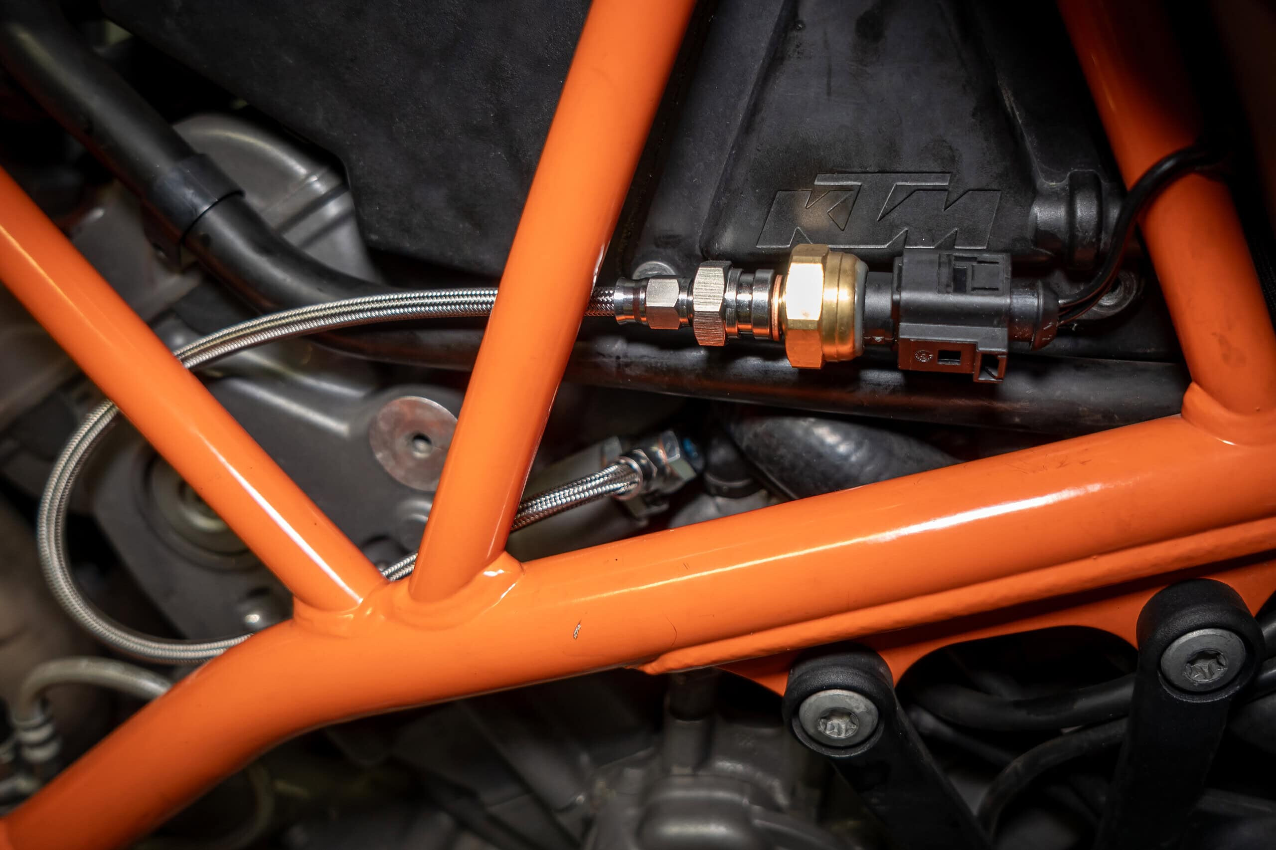
In addition, a banjo fitting with a braided steel hose was installed to allow flexible positioning of the oil pressure sensor.
As with the gear sensor, a switched 12V supply and a signal line to the CUMPAN are also required here. It is recommended to connect the oil pressure signal to analog input 2 (black/blue wire) of the CUMPAN.
Note: In a comparison measurement between the two installation positions, a pressure reduced by approx. 0.5 BAR was measured at the cam chain tensioner (with the engine warm).
Installing the oil pressure sensor (LC4)
Installing the oil pressure sensor is generally also possible on the LC4 engine, but has not yet been tested by us in practice. All that is required is a suitable location or a corresponding thread.
Update: Customers have reported that on models before 2012 it is possible to use the oil filter cover with part number 76038041000 and install the oil pressure sensor in it.
From the 2012 models onward, the oil pressure sensor can be installed in the same position (position no. 31) as on the current models. The following set can be used for this: add-on module oil pressure sensor
Power supply connection
In the final step, the power supply must be connected. This means the CUMPAN, the gear sensor, and, if applicable, the oil pressure sensor are connected to a switched 12V supply. On almost all KTM models, ACC2 connections for auxiliary consumers are already provided by the factory. With the ACC splitters, these connections can be expanded to ensure the required number of slots.
The red positive lead must be plugged into the black/red wire at the ACC2 connection. The black ground lead correspondingly into the brown wire.
Settings on the CUMPAN
Once the 12V power supply has been connected and the correct installation of all components has been checked, the CUMPAN can be switched on with the ignition.
Two settings must be set in the menu:
[MENU] / [SENS] / Damping “250” / Sensor “BIKE”
[MENU] / [INPUT] / IN1 “GEAR” / IN2 “PRESSURE”
All other settings are described in detail in the user manual.
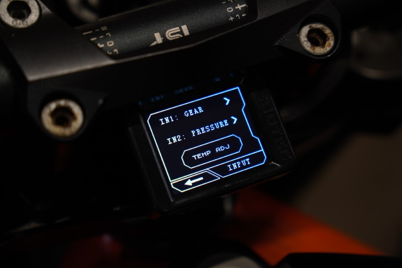

Further background on oil temperature and oil pressure monitoring is summarized in a separate technical article: Monitor oil pressure and oil temperature.
Conclusion: The installation on the KTM 990 Super Duke R serves as a reference for retrofitting a gear indicator and oil pressure monitoring on comparable KTM models with LC8 and LC4 engines. The steps described are structured so that installation locations, wiring, and the CUMPAN menu configuration can be transferred reproducibly to other models.
Products in this article

Top rated

169,90 €
Available immediately

Best sellers

59,90 €
Available immediately

Top rated
179,90 €
Low stock level


